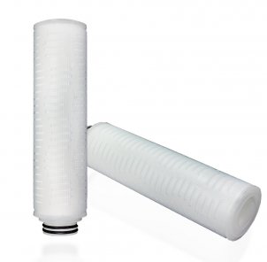
Membrane filter cartridge / sterile filter cartridge, length 10 inches, connection 222 adapter, EPDM seal
delivery time: 1 week
|
||||||||||||||||||||
|
Membrane filter cartridges with hydrophobic PTFE membranes are available with filter ratings from 0.05 ?m to 1.0 ?m. The membrane material has a highly porous structure and a homogeneous pore distribution. All components of the support structure, adapters and end caps are made of polypropylene and are cleaned with the PTFE membrane in the clean room thermally connected without the use of additives or surface-active substances. The filter area is 0.9 m²/10" element and is thus far above the standard of comparable products. This ensures a long service life and low differential pressures even with high throughput rates. Technical specifications - Filter medium: PTFE - Support core: Polypropylene - Adapter and support cage: Polypropylene - Filter fineness: 0.05 - 1.0 ?m - Filter area: 0.9 m²/10" - Temperature: max. 95 °C - Differential pressure: max. 5.6 bar at 20 °C - max. 1.4 bar at 95 °C - Filter change recommended at 1.5 bar - Dimensions: inner diameter 28 mm, outer diameter 69 mm use - Solvent filtration - Sterile ventilation of storage tanks - Coating solutions in the electrical industry - Filtration of non-aqueous chemicals - Filtration of etching baths for semiconductor production Features and Benefits - Hydrophobic, highly porous PTFE membrane - Homogeneous pore distribution - Filter area >0.9 m² at 10" - Excellent chemical resistance - Integrity measurable & sterilizable - Free of binders, adhesives or additives - Long service life, high dirt holding capacity - Low differential pressure, high throughput rates - FDA certified, manufactured in a clean room - Declaration of Food Conformity - REACH Declaration of Conformity |
|
|||||||||||||||||||
Information:
Information:
Information:
Information:
Information:
|
||||||||||||||||||||||||||||||||||||||||||||||||||||||||||||||||||||||||||||||||||||||||||||
Effective CO2 Absorption for a Sustainable Future! |
|
CO2 absorption using lime is a chemical process that involves removing carbon dioxide (CO2) from a gas stream by reacting it with lime (calcium hydroxide). This process is commonly employed in industrial facilities to reduce CO2 emissions and mitigate environmental impact. The CO2 absorption process with lime can be described as follows:- Lime Introduction: Lime in the form of powder or granules is introduced into an absorber or reactor. The absorber is connected to a gas stream containing CO2. - Reaction with CO2: The CO2 in the gas stream reacts with lime, forming calcium carbonate (limestone). The reaction can be represented by the following equation: CO2 + Ca(OH)2 → CaCO3 + H2O. - Formation of Calcium Carbonate: The resulting calcium carbonate is formed as a solid substance and accumulates in the absorber. It can exist as limestone or in other forms. - Removal of Absorbed CO2: To ensure continuous CO2 absorption, the deposited limestone is periodically removed from the absorber. This can be done through mechanical methods such as scraping or chipping. - Regeneration of Lime: The separated limestone undergoes a regeneration stage where CO2 is separated from calcium carbonate. This results in the formation of calcium oxide (quicklime) and CO2. The quicklime can be reintroduced into the absorber to continue the process. The CO2 absorption process using lime offers an effective method for reducing CO2 emissions in various industries such as power plants, cement manufacturing, and other high-emission facilities. By reacting lime with CO2, the greenhouse gas is removed from the gas stream and bound in a solid form, leading to a reduction in CO2 burden. |
Optimize your shopping experience with our detailed delivery information |
Partnership at the highest level. |
|
|
|
|
|
|
|


