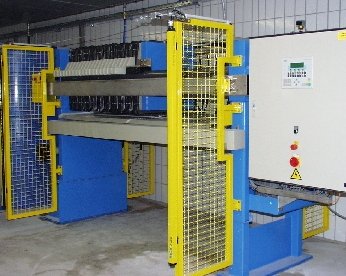
FILTER PRESSESLABORATORY FILTER PRESS - TYPE 250 MINI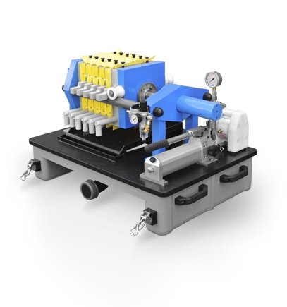 TECHNICAL DATA:Overall dimensions length x width x height) 800 x 600 x 700 mm - clear distance between the stands: 435 mm - weight: approx. 80 kg - filter plate size: 250 x 250 mm - filter cake thickness: 20mm - number of filter plates: 1 + 4 + 1 - number of filter chambers: 5 - spare place for further chambers: 0 - total chamber volume: 2,0 l - filter area: 0,46 m² - outlet: open |
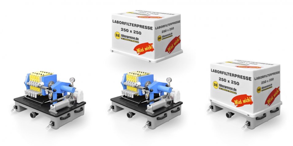
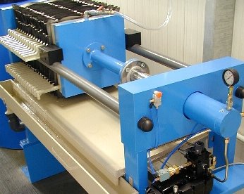
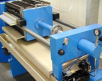
SHORT DESCRIPTIONPress frame The press frame is a sturdy steel construction, the stands being cut from solid material. The side rails are bright drawn and screwed to the rails. The press is fixed onto a plastic substructure, allowing transportation of the machine by common floor-level conveyors (forklift, pallet truck, etc.). Filter plates The press is equipped with polyproylene filter plates. Hydraulic system The hydraulic unit opens and closes the press by retracting and extending the closing cylinder. By means of the hydraulic unit, the closed press is hold on the preset closing pressure. The hydraulic unit consists of a handhydraulic pump with built-in 2/2 way valve. As additional shutt-off facility a further ball valve is installed in the connecting line between hand pump and cylinder. This ball valves closes the cylinder hermetically and helps to avoid unintended opening of the press during operation. The hand pump is a two-stage pump. Up to a hydraulic pressure of 25 bar both pump stages are operating simultaneously, which means that a large quantity of oil will be pumped at low pressure. As soon as a pressure of 25 bar has been reached, the low pressure stage will be switched to idle circulation and the further pressure build-up is realized only by means of the high pressure stage. Cover hood For protecting the filter press during transport and storage, the unit is equipped with a removable plastic hood, which is fixed to the substructure by means of snap locks. Operation side: seen from the hydraulic side over the plate pack on the left. Position of the filtrate discharge: on the operation side, centrally on the bottom. - max. allowed filtration pressure: 12 bar ( 15 bar ) - at least necessary closing pressure: 12 bar up to 405 bar - max. permissible closing pressure: 500 bar Connection data: - nominal diameter at the entry of the slurry: DN 12 (stainless steel screw connection 12 L) - nominal diameter at the filtrate discharge: PP hose connector Da 20 Feature of the filter press - Hydraulic closure, closing manually, opening by spring force. |
|
We offer this laboratory filter press also as rental unit for appropriate test purposes. On request we will be pleased to send you our free and non-binding quote. |
 |
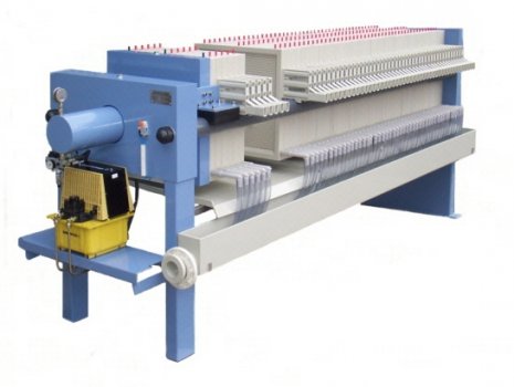 |
IMPORTANT MACHINESIN INDUSTRY, CHEMICAL AND PROCESS ENGINEERINGFilter presses, one of the first units for the separation of solid materials from liquid phases, have already been used more than 130 years ago in England for dewatering clay slurries. Immediately after having discovered the filter press as dewatering unit, many new designs for various applications were developed. Due to the procedural efficiency of filter presses, the current state of the art has made this dewatering unit indispensible in many industrial branches. The recovery of filter presses was facilitated by their automatization. Some special features: - automatic plate shifting device - hydraulic closing unit - improved resp. automated cake release - easy integration into process monitoring and control - reduced downtimes and costs due to significantly improved synthetic filter cloth - increase in throughput performance and reduction of residual moisture, because of high supply pressures, which nowadays are standardized in the pressure stages 6 and 16 bar - automatic filter cloth washing device - squeezing of the filter cakes by means of membrane chamber plates - augmentation up to 1770m² filter aera/filter press |
MODE OF OPERATIONEach filter plate is covered by a filter cloth. All plates are parallelly pushed against each other and then firmly pressed together by means of the closing unit. This creates many parallel cavities, which are interconnected by a feed hole.The filtrate passes through the filter cloth and flows via the grooves in the plates into a collecting pipe and back to the head plate. By means of a feed pump or a pressure vessel the suspension is pressed into the filter unit. The solid material is separated at the filter cloth, where it starts forming a filter cake. As the filter cake becomes thicker, the pressure in the filter chambers increases, which means that under pressure increase the system is constantly filled with suspension up to the set maximum value. We distinguish between the following filter presses in Frame filter presses, chamber filter presses and membrane filter presses. The difference lies only in form and operating principles of the filter elements. Frame filter presses are presses where the filter cake areas are formed from a parallelly ribbed filter plate and a frame corresponding to the thickness of the cake. Chamber filter presses are presses where the cake area consists out of two adjacent hollowed filter plates. Membrane filter presses are characterized by elastic filter plates, either one or both sides of the chamber. So the filter cake can be squeezed once more after filtration. Apart from these basic differences, there are some typical characteristics for filter presses, describing the degree of automation: - manual hydraulic closure or - electrohydraulic closure Especially small filter presses up to a size of 630 x 630 mm do not need an automatic plate shifting device. Perhaps manual plate shifting is still possible with filter presses of the sizes 800 up to 1200 mm, but this is only economical, when for instance one batch per day is processed. In case of processing several batches per day and filter press sizes of 800 x 800 mm or larger, the automatic plate shifting device is in any case recommended. There are two different types of plate shifting devices, the lateral plate transport and the overhead plate transport. In case of lateral plate shifting device, the filter plates are resting on the side rails. They are picked up by appropriate carriers in lateral circulating chains and are then further transported. In case of overhead plate shifting device, the filter plates are hung up in the bridge and then transported. The lateral plate shifting device, which has been used very often in the past, is no longer in compliance with the present state of the art. This is mainly due to the great difficulties that may arise, when working with the laterial shifting device. In particular must be appointed the tilting of the filter plates. Moreover, sidewords conveyed filter plates are swinging on their transport way, which causes an increased wear of filter cloth. Another disadvantage of such shiffting devices is the restricted accessibility to the filter plates. Therefore the overhead plate shifting device is to be preferred. When choosing the filter plate shifting device, it is necessary to make sure, that the plates are picked up at only one point, in order to avoid tilting. It is most important to interlock the filter plates, ensuring that only one plate will be moved. Short example for such a system: The plates are hanging in so called carts in the bridge. The wide deflection of the carts prevents the filter plate from swinging lengthways, while swinging sideways is prevented by means of guide rods. So called locking hooks secure the complete plate package. Each plate latches with a hook into the cart of the plate in front. |
   |
 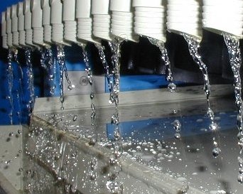 |
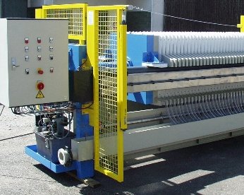
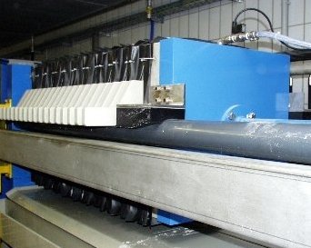
AUTOMATIC FILTER CLOTH CLEANING STATIONThe filter cloths are polluted by particles, flowing through the fabric during the filter process. Depending on how fast and how strong a certain product contaminates or clogs the filter cloths, they need to be cleaned weekly or at least monthly. So far the filter cloths have been cleaned usually by removing them from the plates and washing them in a washing machine. Then they need to be fastened again to the filter plates. It is not reasonable to leave the filter cloth on the plates and clean them by means of a transportable steam jet unit with spraying lance. On the one hand, these units will not clean the filter cloth sufficiently and on the other hand a lot of splashing water together with the detached slurry will pollute the entire room. Cleaning of the filter cloths will be done nowadays by means of integrated filter cloth cleaning stations. These cleaning stations are working with a pressure of 100 bar and consist mainly of a stainless steel U-profile, moving along the overhead bridge of the press. During the cleaning process, the first plate with filter cloth is positioned in the middle of the opening stroke. The automatically controlled spraying device moves from its position to the first plate to be cleaned. When the device has reached this position, the nozzle tube being attached all around the plate is lifted up to the top edge. Here it stops and goes back. The filter plate centers automatically, due to the same water pressure on both sides. So damages of the filter cloth can definitely be excluded. The first plate being cleaned, the sprayng device moves on to the next plate. The cleaned plate moves to the thrust piece and the next plate is drawn automatically into washing position. From here, this cycle is automatically repeated until the end of the plate package. A filter press 1200 x 1200 with 100 chambers for instance can be cleaned by means of such a station in approx. 1,5 hours. |
SELECTION CRITERIAAfter having determined the quantities being filtered and their dry substance content, at first the required size of the filter press has to be specified. Usually there are three different ways for preparing the layout: - Referring to comparative values from existing plants processing the same products. - If no values based upon experience are available for the material to be dewatered, or the cost estimate must be very detailed already in planning stage, the specific filter capacities have to be determined empirically, in other words, by means of dewatering tests. Therefore some suppliers have mobile testing facilites available. - By estimating the filter time and the achievable dry content, it is possible to calculate the necessary chamber volume with the help of the sediment budget. Based on one of the 3 ways and the resulting filter areas, it will be possible to determine the press size. It is to be noted, that the sizes of the filter presses are overlapping each other in large parts with regard to the constructionally possible filter areas. Hence, the size depends on many other factors, e.g. design of the building or available working time. After that, plate material, closure type of the plate package and plate shifting system can be selected. The filter press manufacturer will assist you with the budgeting process. |
 |
POTENTIAL APPLICATIONSLiquid and solid phases in the filter press have already been mentioned. The filter cloth holds back the solid particles and due to the post-flow of further solid-liquid mixtures follows a nesting of particles in different sizes and shapes. The permanent post-flow creates drag and shear forces, which will sort the particles in such a way that voids between bigger parts are filled up by smaller parts. Nevertheless, the structure of the cake layer must leave capillaries to allow further flow through of liquids. The structure of some solid-liquid mixtures however doesnt allow post-flowing. In such cases have to be added to the suspension so-called supporting structure formers. For this purpose, various options are possible. Coal, ash, stone powder, limestone, etc. are commonly used. Sometimes are even used organic flocculants, mainly when the ultra-fine particles carry along a high percentage of water and are not able to build up a permeable cake layer. By means of hydrophobizing single particles are tied up to a particle chain. |
The advantage of pressure filtration is a very clear filtrate, as the filter plates all around with the cake layer avoid further penetration of even finest material parts. In fact, this layer is building up, until the filter chambers are filled. During this process grows the filter resistance of the cake layer. Each pressure filtration operates according to a special function, which varies depending on different factors. In general, suspensions with high solids load will build up a cake much quicker than a suspensions with low solids load. This time however depends on a variety of other conditions, e.g. particle size, distribution and structure, specific gravcity, viscosity, compressibility, etc. A safe estimate can only be given, when all these boundary conditions are known. Beyond that rapidity of the filtration process and thus also the specific capacity of the filter is determined by variable parameters of the filter itself, such as thickness of the cake, pressure, shape of the chambers and pressure feeding speed. These parameters can be custom-designed for specific applications. |
| Anyway the filterpress is a filtering unit, which can easily and in various ways be adjusted to the nature of the product resp. to the product and project requirements. Such requirements might be for instance to free the cake after filtration from dissolved salts of the parent solution, in order to use further the parent solution or to keep the cake free from salt.
For this, the filter press offers various possibilities as well: The salts located in the capillaries of the cake can be „washed out“. Thereby the parent solution in the cake will be replaced by following water. Two methods with some variants have proved to be effective: - counter-flow washing system - continuous-flow washing system |
When using the counter-flow washing system, the washing liquid is pressed on one side into every second chamber and flows then into the rib channels of every second plate. From here the water can only flow through the capillaries of the cake to the rib channels of the adjacent plate. So the parent solution is displaced and replaced by the washing liquid. The drained off liquid is channeled through the rib channels of the adjacent plate to the head plate of the filter press.
When using the continuous-flow washing system, exchange of the liquids is carried out in the same manner, while the washing liquid however takes the same way than the suspension fed into the system before. Which one of the two processes will be more efficient for a special product, depends mainly on the structure of the particles. In many cases the washing procedure is completed by the so called blow-dry process, which means that an air flow removes remaining water from the cake. |
| For the washing as well as for the blow-dry process it has to be stated, that an optimum flow-through requires a homogeneous cake build-up. Otherwise there is a risk of the so-called preferred washing channels, which might cause cracks or holes in the cake. They are also termed as bypasses, allowing the following media to pass through easily, while other parts of the cake are not sufficiently fed. However, only for some products the formation of bypasses is likely.
The formation of bypasses can be excluded as far as possible by using membrane plates. Before washing the cake will be homogenized through the membrane, however homogenization of the complete filter area is most important. For this purpose the suspension supply has to be transferred outside the filter area. Designs with centric suspension supply are less suitable. copyright by Dipl. Ing Bernd Kirchner |
Besides, membrane plates are outstandingly suitable for the compression of filter cakes after filtration. A static pressure is applied onto the cake. Some products show a significant increase in residual moisture content, which is achievable in the cake. This is due to the exchanged force direction onto the cake build-up, as compared to the force directions during filtration, which are only in parts vertically. By the force exerting vertically to the cake, any bridges between the particles will be destroyed, rearranged and nested.
It is worth mentioning that filter presses offer a broad range of application possibilities, because they meet special machinery requirements. With a minimum of moving parts filter presses are exceptionally wear resistant. Corrosion problems can be eliminated by taking appropriate protective measures, the maintenance and operating costs are limited to an absolute minimum. Furthermore the filter press is probably that unit in separation technology offering the greatest filter area per room space. For instance, 1770 m² filter area need an installation surface of approx. 60 m². |
Optimize your shopping experience with our detailed delivery information |
Partnership at the highest level. |
|

|

|


|


|
|


|

