PRESSURE LOSS IN PIPE SYSTEMS OUT OF PLASTIC


Pressure loss coefficients for fittings and molded parts made of PVC U and ABS


In hydraulic pipeline calculations pressure loss coefficients are necessary for the calculational determination of fittings. The pressure losses resulting from friction-, deflection- and separation losses play a considerable part in the total pressure loss of a pipe system. In order to determine the pressure loss in fittings as easily as possible, in the annex "pressure loss coefficients for PVC-U / C and ABS fittings" are shown in meter/fitting. When calculating the pressure loss of the individual pipe length, these values have to be considered as equivalent length of the straight pipe length LR.


Pressure losses in straight pipe runs are calculated as follows:


If for certain fittings no pressure loss coefficients are available, the following calculation formula can be taken as a basis


The Zeta values can be read in the usual charts.


PRESSURE LOSS IN FITTINGS


- Indication in meter equivalent pipe / fitting -


PVC-U / PVC-C Fittings ABS Fittings
d 90° Elbow 45° Elbow 90° Bend Tee (1) Tee (2) 90° Elbow 45° Elbow 90° Bend Tee (1) Tee (2)
16 0,40 0,10 0,10 0,10 0,80 0,39 0,13 0,13 0,13 0,78
20 0,50 0,10 0,10 0,10 1,00 0,50 0,17 0,17 0,17 1,01
25 0,70 0,15 0,20 0,20 1,30 0,64 0,21 0,21 0,21 1,27
32 0,90 0,20 0,20 0,20 1,80 0,83 0,28 0,28 0,28 1,67
40 1,10 0,40 0,30 0,30 2,20 1,04 0,35 0,35 0,35 2,08
50 1,30 0,50 0,40 0,40 2,80 1,30 0,43 0,43 0,43 2,59
63 1,80 0,80 0,50 0,50 3,60 1,64 0,55 0,55 0,55 3,28
75 2,00 0,90 0,70 0,70 4,30 1,95 0,65 0,65 0,65 3,90
90 2,40 1,10 0,80 0,80 5,10 2,34 0,78 0,78 0,78 4,68
110 3,00 1,30 1,00 1,00 6,30 2,86 0,95 0,95 0,95 5,72
125 2,50 1,50 1,20 1,20 7,40 3,26 1,09 1,09 1,09 6,52
140 2,90 1,80 1,30 1,30 8,30 3,64 1,21 1,21 1,21 7,28
160 4,50 2,00 1,50 1,50 9,60 4,17 1,39 1,39 1,39 8,34
180 5,00 2,00 1,70 1,70 10,70 5,40 1,80 1,80 1,80 10,80
200 5,60 2,50 1,90 1,90 11,90 5,21 1,74 1,74 1,74 10,42
225 6,20 2,80 2,10 2,10 13,40 5,86 1,95 1,95 1,95 11,72
250 6,90 3,10 2,30 2,30 14,80 6,53 2,18 2,18 2,18 13,07
280 7,80 3,50 2,70 2,70 16,80 8,40 2,80 2,80 2,80 16,80
315 8,70 4,00 3,00 3,00 18,80 8,20 2,73 2,73 2,73 16,40
 
(1) Volume flow in the passage direction
(2) Volume flow from the outlet in the passage direction
The equivalent pipe lengths of the molded parts are to be added to the straight total pipe length during the pressure loss calculation.
The resistance coefficients for PE and PP molded parts can be requested from us if necessary.


Pressure drop in PVC U pipelines, pressure stage PN 16, medium: water 20°C


  d 75 X 5,6 d 90 x 6,7 d 110 x 8,2 d 125 x 9,3 d 140 x 10,4
Q
[l/s]
V
[m/s]
delta p
[bar/100m]
V
[m/s]
delta p
[bar/100m]
V
[m/s]
delta p
[bar/100m]
V
[m/s]
delta p
[bar/100m]
V
[m/s]
delta p
[bar/100m]
0,16 0,050 0,0009                
0,2 0,063 0,0014                
0,25 0,078 0,0020 0,054 0,0008            
0,315 0,099 0,0029 0,068 0,0012            
0,4 0,125 0,0044 0,087 0,0019 0,058 0,0007        
0,5 0,156 0,0065 0,108 0,0027 0,073 0,0011 0,056 0,0006    
0,63 0,197 0,0097 0,137 0,0041 0,092 0,0016 0,071 0,009 0,056 0,0005
0,8 0,250 0,0148 0,174 0,0062 0,116 0,0024 0,090 0,0013 0,072 0,0008
1 0,313 0,0218 0,217 0,0091 0,145 0,0035 0,112 0,0019 0,090 0,0011
1,25 0,391 0,0323 0,271 0,0135 0,182 0,0052 0,141 0,0028 0,112 0,0017
1,6 0,500 0,0499 0,347 0,0208 0,233 0,0080 0,180 0,0044 0,143 0,0025
2 0,626 0,0741 0,423 0,0309 0,291 0,0119 0,225 0,0064 0,179 0,0038
2,5 0,782 0,1102 0,542 0,0459 0,363 0,0176 0,281 0,0095 0,224 0,0056
3,15 0,985 0,1665 0,684 0,0692 0,458 0,0265 0,354 0,0144 0,282 0,0083
4 1,251 0,2555 0,868 0,1060 0,581 0,0405 0,450 0,0219 0,358 0,0127
5 1,564 0,3819 1,085 0,1582 0,727 0,0603 0,526 0,0326 0,448 0,0189
6,3 1,971 0,5802 1,367 0,2398 0,916 0,0913 0,709 0,0493 0,565 0,0286
8 2,502 0,8958 1,736 0,3693 1,163 0,1403 0,900 0,0757 0,717 0,0438
10 3,128 1,3466 2,170 1,453 0,2099 1,125 0,1131 0,1131 0,896 0,0654
12,5     2,712 0,8319 1,817 0,3146 1,406 0,1692 1,120 0,0978
16     3,472 1,3078 2,325 0,4931 1,799 0,2649 1,434 0,1529
20         2,907 0,7416 2,249 0,3977 1,792 0,2293
25             2,812 0,5982 2,240 0,344
31,5                 2,823 0,5258
 
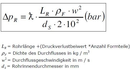
Subject to technical modifications, all data without guarantee


The above listed values and charts are an excerpt. Detailed calculations you will find under the following link: pressure loss in pipelines


Layout of plastic pipe systems


- Flow calculation -


In our drop-down menu "ONLINE-TOOLS", next to the article description, you will find a link to the flow calculation of plastic pipelines.

For a rough planning of your project, this function is very helpful.


Optimize your shopping experience with our detailed delivery information


Plastic pipe systems


Overview of plastic pipe systems
Technical information on ABS pipe systems
Technical information on PVC  U pipe systems
Technical information on PVC  U transparent pipe systems
Technical information on PVC  C pipe systems
Technical information on PP pipe systems
Technical information on PP-R pipe systems
Technical information on PE pipe systems
Technical information on PVDF pipe systems

Chemiedur - pipe


Technical information on UP-GF (FRP) pipe systems
UP-GF (FRP) pipes
UP-GF (FRP) molded parts and connection
UP-GF-PP (FRP) molded parts and connection
UP-GF (FRP) adhesive collars
UP-GF (FRP) loose flanges
Pot Strainer DN 200 - DN 500 Inliner PP/FRP Coated
Pot Strainer DN 200 - DN 500 Inliner FRP/CBL Coated
Angle Seat Strainer DN 200 - DN 400 Inliner FRP/CBL Coated
Manhole mad of FRP and PP/FRP

Plastic pipes


Calculator for cutting pipes
Guidelines for sawing plastic pipe
Leftovers in plastic pipe
Standardization of plastic pipes and molded parts
PVC U pipes deviations
Pressure loss in pipe systems out of PVC U, PVC C and ABS pipe systems
Distinction between Rp, R and G threads
Screw lengths for flange connections

Plastic fittings


PVC U transparent ball valves
Diaphragm valves
Block valves
Butterfly valves
Plastic needle valves


Plastic Valves according to ATEX


New EU guideline 2014/34/EU
Plastic Valves in EX zones
Y-Strainers PP-EL DN 15 - DN 50
Check valves PP-EL DN 15 - DN 50
Angle seat valves PP-EL DN 15 - DN 50

Bonding of plastic pipes


Bonding manual
Video showing the bonding of pipes

Plastic welding


Guidelines for extrusion welding


Grids / support grids


GFK grids
Grids out of PP -el electrically conductive
Profile support grids out of PP -el electrically conductive


Molded ventilation parts


Ventilation technology


Chemical hose


PVC transparent hose with fabric inlay


Industrial tanks and chemical containers


Dosing tanks and outer containers 35 – 1000 Liter
Salt dissolving tanks 60 -5000 Liter
Storage tanks and vats
Storage tanks for water
Safety and collecting troughs
Industrial tank delivery program
Dosing tanks with agitator
Dosing tank agitators
Dosing tanks with attachments
Dosing tanks made of sheet material
Customized chemical containers
Dosing tanks with level indicators


IBC TANKS/CONTAINERS


IBC screw caps DN 150/DN 200
IBC adapters out of PE
IBC adapters out of PP
MULTI FLEX BLOCK for IBC BULK CONTAINER


Attachment parts for tank construction


Vapor separators
CO2 - absorbes
Manholes
Revision nozzles
Block flange

Filter housings and filter cartridges


PENTEK 3G Slime Line filter housings
PENTEK 3G Standard filter housings
PENTEK Big Blue filter housings
PENTEK PP high temperature filter housings
PENTEK PP all nature filter housings
PENTEK filter bags for Big Blue filter housings
PENTEK surface filter cartridges
PENTEK filter cartridges for depth filtration
PENTEK filter cartridges with activated carbon
CINTROPUR filter systems
CINTROPUR water filters

Flange configurator


Blind flanges, loose flanges,  rectangular flanges

Chemical resistance


Table of chemical resistance for plastic pipe systems
 

Machined plastic parts


Inserts
Screw-in parts
Threaded fittings
Screw fittings

Milled plastic parts


Loose flanges and blind flanges made of sheet material

Static mixers


Static mixers made of plastic

Strainers


Single-type and double-type strainers
Pot strainer DN 300
Angle seat strainer DN 500


Flow meters


Variable area flow meters
Configuration tool for flow meters

Filter presses


Laboratory filter presses

Injection molded parts


Scraper made of PE for filter press

Kwerk Practice Blog


The Kwerk team blogs from the field here


Partnership at the highest level.


ONLINE TOOLS
REQUEST A QUOTE
STARTING A PROJECT REQUEST